Showing posts with label 802.11 frame format. Show all posts

Nov 27, 2016

Very High Throughput (VHT) in 11ac

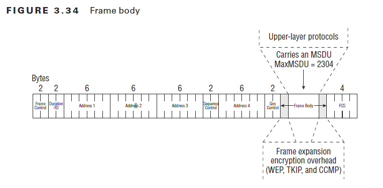
802.11ac maintains the frame format used by its predecessors. There are two major changes. First, 802.11ac extends the maximum frame size from almost 8,000 bytes to over 11,000 bytes. Second, it reuses the HT Control field from 11n, but does so by defining a new form of the Control field. When the HT Control field begins with a 0, the format is identical to 802.11n and the HT Control field is of the HT-variant type. When the HT Control field begins with a 1, the HT Control field is of the VHT-variant type.


Management Frames

Management frames signal that they are capable of building an 802.11ac network or participating in an 802.11ac network by including the VHT Capabilities Information element. This element is placed in Probe request and Probe response frames to enable client devices to match their capabilities to those offered by a wireless network. The VHT Capabilities Information element, as shown in the following picture, is the core information element used in management frames to set up operation of 802.11ac networks. 


The VHT Operation Information element 

All 802.11 physical layers have an information element (IE) that describes their operation, and the VHT PHY is no exception. The VHT Operation IE, show the following picture, describes the channel information and the basic rates supported by the transmitter.


The following figure shows VHT Capabilities information element in Beacon. The key thing to look for is the number of lines that read "10". A line that reads "10" indicates that a spatial stream is available. A line that reads "11" indicates that no spatial stream is available. That means if three lines read "10" and the remaining five lines read "11", then there are three spatial streams available for my AP.


What does that mean for data rates?

1 spatial stream: 6.5 Mbps to 433 Mbps data rates
2 spatial stream: 6.5 Mbps to 867 Mbps data rates
3 spatial stream: 6.5 Mbps to 1.3 Gbps data rates


Reference 
https://sniffwifi.wordpress.com/


Oct 19, 2016

Frame Body and FCS Field

There are three major 802.11 frame types: management, control, and data frames. Only 802.11 data frames carry an MSDU payload in the frame body. The frame body is of variable size. As you could see the following picture, the maximum frame body size is determined by the maximum MSDU size (2,304 octets) plus any overhead from encryption. The 802.11n-2009 HT amendment defi nes a frame aggregation method called Aggregate MAC Service Data Unit (A-MSDU). An 802.11n station using this method of aggregation can have a frame body with a maximum A-MSDU size (3839 or 7935 octets, depending upon the STA’s capability), plus any overhead from encryption.

above the picture from CWAP

The frame check sequence (FCS) also known as the FCS field contains a 32-bit cyclic-redundancy
check (CRC) that is used to validate the integrity of received frames. As you could see the following picture, the FCS is calculated over all the fields of the MAC header and the Frame Body field.


                                                                            above the picture from CWAP 

If any portion of a unicast frame is corrupted, the CRC will fail, and the receiving 802.11 radio will not send an ACK frame to the transmitting 802.11 radio. If an ACK frame is not received by the original transmitting radio, the unicast frame is not acknowledged and will have to be retransmitted.

QoS Control Field

The QoS Control field is a 16-bit field that identifies the quality of service (QoS) parameters of a data frame. In other words, the QoS control field is only used in the MAC header of QoS data frames.

As shown in Table 3.4, the QoS Control field is comprised of five subfields called traffic identifier (TID) subfield, end of service period (ESOP) subfield, ACK policy subfield, and a reserved subfield.


The first sub field of the QoS control field is the 4 bit TID. The traffic indicator (TID) subfield is used to identify the user priority (UP) and traffic access category of the QoS data frame.

User Priority (UP) level points wired 802.3 Ethernet network and Access Category points Wi-Fi Multimedia Access Categories.


Above pictures from CWAP

For example, a TID subfield could indicate a UP of 6, meaning that access category would be for voice traffic.

The ESOP subfield is 1 bit in length and is used by the access point to indicate the end of the current service period (SP). The last frame sent during the service period will have the bit set to a value of 1 to tell the WMM-PS client station that either the service period is over or that the AP’s buffer is empty. The WMM-PS client station can then go back asleep.

The fourth subfield of the QoS Control field is 1 bit and is currently reserved for future use.

The fifth subfield of the QoS Control field is 8 bits in length and can be used for a variety of purposes. The fifth subfield can be used as a TXOP Limit, an AP PS Buffer State, a TXOP Duration Requested, or a Queue Size.

Sequence Control Field

The Sequence Control field is a 16-bit filed comprising two subfields. The fields are a 4-bit fragment number and a 12-bit sequence number.


above the picture from CWAP

All 802.11 stations can be configured with a fragmentation threshold. If the fragmentation threshold is set at 300 bytes, any MSDU larger than 300 bytes will be fragmented. See the following picture, as the example. 

above pictures from CWAP


MAC Layer Addressing


Much like in an 802.3 Ethernet frame, an 802.11 MAC sublayer address is one of the fol-lowing two types:

  • Individual Address Assigned to a unique station on the network (also known as a unicast address).
  • Group Address A multiple-destination address, which could be used by one or more stations on a network. There are two kinds of group addresses:
    • Multicast-group Group Address An address used by an upper-layer entity to define a logical group of stations.
    • Broadcast Address A group address that indicates all stations that belong to the net- work. A broadcast address, all 1 bits, is received by all stations on a local area network. In hexadecimal, the broadcast address would be FF:FF:FF:FF:FF:FF. 
The following picture shows four 802.11 MAC address fields respectively called Address 1, Address 2, Address 3, and Address 4. Depending on how the To DS and From DS fields are used. 


above the picture from CWAP

See the packet capture as the example from the post - MAC header - Frame Control - "To DS" and "From DS" .


You maybe ask when 4 addresses are used. One of examples is WDS: WLAN bridging. 
Above the picture from CWAP

Duration / ID Field

The Duration / ID field is 16 bits in length . The Duration ID field can be used for three difference reasons.

  • Virtual Carrier Sense: The main purpose of this field is to rest the NAV timer of other stations.
  • Legacy power management: PS-Poll frames use the field as an association identifier (AID)
  • Contention-free period: Point coordination function (PCF) process has begun
Above the picture from CWAP

Virtual Carrier Sense uses a timer mechanism known as the Network Allocation Vector (NAV). 
As you con see the following picture, when the receiver hears a frame transmission from the sender, it looks at the header of the frame and determines whether the Duration/ID field contains a Duration value or an ID value. If the field contains a Duration value, the listening station will set its NAV timer to this value. The receiver will then use the NAV as a countdown timer, knowing that the RF medium should be busy until the countdown reaches 0.

Above the picture from CWAP


The second way for Duration/ID field is used for power management process. The access point uses this AID to keep track of the stations that are associated and the members of the BSS. If

the access point is buffering data for a station in Power Save mode, when the access point
transmits its next beacon, the AID of the station will be seen in a field of the beacon frame
known as the traffic indication map (TIM). The TIM field is a list of all stations that have
undelivered unicast data buffered on the access point waiting to be delivered. The following picture shows that PS-Poll frame the Duration/ID field will now be used as an AID value.

Above the picture from CWAP


                                                                          Above the picture from CWAP


As you can see that 2^15- 1 == 32767,  2^14 -1 == 16383 and from 2008 - 16383 are reserved 

MAC header - Frame Control - Protected Frame Field and Order Field

The following picture shows the position of the Protected Fame field in the MAC header.

above the picture from CWAP

When the Protected Frame field is set to a value of 1 in a data frame, the MSDU payload of the data frame is indeed encrypted.  As the following picture, we could see that ARP is encrypted when Proctected flag = 1.


On the other hand, The majority of management frames are never encrypted, therefore the Protected Frame field will be set to 0. As the following picture, we could see that ARP is not encrypted when Proctected flag = 0.


The order field is set to 1 when a higher layer has requested that the dat be sent using strictly ordered class of service, which tells the receiving station frames must be processed in order. The field is set to 0 in all other frames. 

Oct 17, 2016

MAC header - Frame Control - Power Management Field and More Data Field

When a client station is set for Power Save mode, it will shut down some of the transceiver components for a period of time to conserve power. When the Power Management bit is set to 1, the access point is informed that the client station is using  power management, and the access point buffers all of that client's 802.11 frames.

wlan.fc.pwrmgt == 1

A value of 0 means that no power management is being used, and therefore no buffering is needed.

                                            wlan.fc.pwrmgt == 0

Above the picture from CWAP


Any time a station associates to access point,  the station receives an association identifier (AID). The access point uses this AID to keep track of the stations that are associated and the number of the BBS. If the access point is buffering data for a station in Power Save mode, the AID of the station will be seen in in afield of the beacon from know as the traffic indication map. 

As shown in the following picture, when access point sends the data to the station, the station needs to know when all of the buffered uni-cast data has been received so that it can go back to sleep. Each unicast frame contains a 1-bit field called the More Data field.

To summarize, the More Data field is used to inform Power Save mode clients that they still have buffered unicast traffic and they should not go back into a doze state. 


Oct 16, 2016

MAC header - Frame Control - Retry Field

If the Retry Field bit is set to 0, an original transmission of the frame is occurring. If the Retry Field bit is set to 1 in either a management or data frame, the transmitting radio is indicating that the frame being sent is a retransmission.

above the picture from CWAP

In MAC Layer service, if the 802.11 frame is received properly and CRC of the FCS passes, the 802.11 radio that received the frame will reply with ACK frame.
IF the ACK is received, the original station knows that the frame transfer was successful. Almost all unicast 802.11 frames must be acknowledged for delivery verification purposes. Broadcast and multicast frames do not require an acknowledgment. 

wlan.fc.retry == 0

If any unicast frame is corrupted, the CRC will fail, and the receiver will not send ACK from to the sender. If an ACK frame is not received by the sender, the sender will retransmit the data frame. Im most cases, unicast frames must be a acknowledged by an ACK or Block ACK frame.
wlan.fc.retry == 1

Excessive layer 2 retransmission affect the WLAN int two ways.
  • Layer 2 retransmissions increase overhead and therefore decrease throughput
  • If application data has to be retransmitted at layer 2, the timely delivery of application traffic becomes delayed or inconsistent

In the following picture, we track retry statistics.

Layer 2 retransmissions are result of many possible problems, such as, Multipath, RF interference, and low SNR. Also hidden node, near/far, mismatched power settings, and adjacent cell interference 

MAC header - Frame Control - More Fragments

The More Fragment filed is 1 bit in length. a


above the picture from CWAP

The More Fragments field is set to 1 if another fragment of the same MSDU follows in a subsequence frame. It is set to 0 in all other frames. The following packet capture show More Frame is 1


Notice that MAC layer never fragment broadcast and multicast frames because frames sent to a multicast are never acknowledged and retransmitted in any event. The following packet capture show More Frame is 0


MAC header - Frame Control - "To DS" and "From DS"

The "To DS" and "From DS" indicate the flow of the 802.11 data frames between a WLAN environment and the distribution system (DS).

Above the picture from CWAP

There are four possible combinations for "To DS" and "From DS" as summary in the following table.


To DS = 0 and From DS = 1
It indicates that an 802.11 data frame is being sent downstream from an access point to a client. For example, a DHCP offer packet through an AP to a client station.

To DS = 1 and Frome DS = 0
It indicates that an 802.11 data frame is being sent upstream from a client station to an access point. For example a client station sending DHCP request packet through an AP to DHCP server.
 

Oct 15, 2016

MAC header - Frame Control - Protocol Version, Type and Subtype

The first two bytes of the MAC header is called as Frame Control Field, which includes Protocol Version, Type, SubType, To DS, From DS, More Fragments, Retry, Power Management, More Data, Protected Frame, and Order. As you could see from the following picture.

Above the picture from CWAP

Protocol is a 2 bit field at the beginning of MAC heard. After protocol version, the Type field and Subtype file are used to identify the function of the frame. 

The following wireless packet capture shows the these three fields 


All 802.11 frames aways set Protocol Version as 0. All other values are reserved. 
There are 4 types fames, as the following 

Above the picture from CWAP

The subtype field are 4 bits and the combinations are shown as the following,
Above pictures from CWAP

At last, I list Filters of wireshark for these three fields
wlan.fc.version  ----> Proctocol version
wlan.fc.type      ----> Type
wlan.fc.subtype ----> Subtype

MAC Header - General

   In the last post, we introduced 802.11 MPDU consists "MAC Header", "Frame Body", and "Frame Check Sequence".  Follow posts, we will focus on MAC header which has frame control, duration, addressing and so on.

Above the picture from CWAP


Note that if all the field are used, the maximum size of an 802.11 MAC header is 32 bytes. But, the 802.11n adds a new field to the 802.11 MAC header, called the HT Control field which has 4 byte long. If the HT Control field is used, the maximum size of 802.11 MAC header would be 36 bytes. The size of an 802.11 MAC hear is not always the same for two reasons. First, the QoS Control field is used only in QoS Data frames. Second, no every fame use all four fields. For example the follow MAC header has 24 bytes which has only three addresses (Transmitter address and Source address are the same) and no QoS Control Field. 


Oct 14, 2016

Data-Link Layer

The 802.11 Data-Link layer is divided into two sublayers

  • Logical Link Control (LLC) sublayer 
  • Media Access Control (MAC) sublayer
When Network Layer sends data to Data-Link layer, the data is handed off to the LLC and becomes known as the MAC Service Data Unit (MSDU). When LLC sends the MSDC to the MAC layer. Then MSDU is now encapsulated in a MAC Protocal Data Unit (MPDU)


Above two pictures are from CWAP

Let see the real wireless data from wireless packet capture.  

The data from 88 to 00 (mark as the blue color) is MAC header and the data from 79 to 65 is FCS. The rest of parts (from aa to 65) is Fame body.