Oct 22, 2016

Acknowledgement Frame

Since 802.11 stations are not able to transmit and receive at the same time, when a station is transmitting a frame, it is not able to determine whether the frame was received or whether there was a collision. Therefore, every time an 802.11 radio transmits a unicast frame, the 802.11 radio that received the frame will reply with a ACK frame. 802.11 is also capable of sending a single acknowledgement for multiple unicast frames.

IF the ACK is received , the original station knows that the frame transfer was successful. All unicast 802.11 frames must be acknowledge. Broadcast and multicast frames do not require an acknowledgement. 

IF any portion of a unicast frame is corrupted, the CRC will fail and the receiving 802.11 radio will not send an ACK from to the transmitting 802.11 radio. If an ACK frame is not received by the original transmitting radio, the unicast frame is not acknowledged and will have to be retransmitted. 

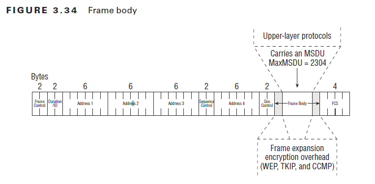
The following picture display the frame format for the ACK frame. 

above the picture from CWAP


Again if an ACK frame is not received by the original transmitting radio, the unicast frame is not acknowledge and will have to be retransmitted. 
Excessive layer 2 retransmissions adversely affect the WLAN in two ways:
  • Layer 2 retransmissions increase overhead and therefore decrease throughput. 
  • If application data has to be retransmitted at layer 2, the timely delivery of application traffic becomes delay or inconsistent.

Extended Rate PHY (ERP) Element

The ERP element is present only on 2.4Ghz networks supporting 802.11g and is present in beacons and probe response.


ERP is essential to the operation of 802.11b/g/n networks. 

The Non_Present bit is set to 1 if at least one of the following conditions
  • A Legacy 802.11b client associates to the cell
  • A neighboring cell is detected, allowing only nonERP data rates. This detection is expected to occur by receiving a beacon from the neighboring cell.
  • Any other management frame is received from a neighboring cell supporting only nonERP data rates.

The UseProtection bit is set to 1 as soon as nonERP client is associated to the cell. 

The nonERP present bit is set to 1 only if the AP detects a non-ERP station in the cell. If the AP detects a beacon from a neighboring AP having the UseProtectioin bit set to 1, there may be a nonERP station in neighboring cell that can impact the traffic of the local cell clients in the direction of this neighbor, even if the local AP does not hear the nonERP client directly.


A common misconception is that 802.11g radios revert to 802.11b data rates when the pro- tection mechanism is used. In reality, ERP (802.11g) radios still transmit data at the higher ERP-OFDM rates. However, when an HR-DSSS (802.11b) station causes an ERP (802.11g) BSS to enable the protection mechanism, a large amount of RTS/CTS or CTS-to-self over- head is added prior to every ERP-OFDM data transmission. The aggregate data throughput loss is caused by the extra overhead and not by using slower 802.11b rates. A data rate of 54 Mbps usually will provide about 18–20 Mbps of aggregate throughput when protection is not enabled. After protection is enabled, even though the ERP STA may be transmit- ting frames at ERP rates, the overhead of protection will likely reduce the aggregate data throughput to below 13 Mbps and possibly as low as 9 Mbps. 

Traffic Indication Map (TIM) Element

Traffic Indication Map is present only in beacon. The TIM element contains information useful for clients in low-power mode.


Besides the classical element ID and length, the TIM contains two types of elements: The virtual bitmap and DTIM information. 

The DTIM is not present in all beacons and all TIMs. The beacon will contain a TIM that will also be a DTIM (Delivery Traffic Indication Message). AP uses the beacon frames DTIM information to inform the cell if it has broadcasts or multicasts frames buffered. Stations in low power mode should wake up at least for every beacon that is a DTIM. The DTIM does not have to be in every beacon but can, for example, occur every two to five beacons.

When a DTIM shows that there is broadcast or multicast traffic buffered at the AP level, all stations stay awake. Just after sending the beacon announcing that buffered broadcast or multicasts that AP contends for the medium and then forwards the buffered broadcast or multicast to the cell. All stations recevied it and then can go back to sleep if needed. 

The first bit of the bitmap control field is used to announce the presence of multicast or broadcast traffic buffered on the AP. 


When Bitmap Control field is set to 1, the AP has multicast or broadcast buffered. When this first bit is set 0, there is no buffered broadcast or multicast. 


Reassociation Request / Response Frame

Reassociation Request frame can be sent only by the client to access point and is used when the client is already associated to the ESS and wants to associate to another access point.

The follow pictures show the reassociation request frame format and Elements
above the pictures from CWAP

In this logic, the client leaves the coverage area of an access point and needs to associate to another access point offering the same SSID. This roaming station goes through the authentication phase with the new access point, then sends a reassoication request mentioning the old AP MAC address, and finally joins to the new AP, getting a new AID. 

Why not proceed with a simple association request frame?  It is because the logic is that the new access point should contact the old access point and move the parameters for the station from the old AP to the new one. 

A client can be authenticated to server access points, as long as it is associated to only one of them. 

An AP uses the reassociation response frame in response to a reassociation request frame. The reassociation response contains the elements

Above pictures from CWAP

The difference between association frame and re-assoication frame is 
 - With association request/response, the client gets an AID on the local AP
 - WIth reassociation request/response, the client have to move from the old AP to the new AP. 

Oct 21, 2016

Disassociation Frame and Deauthentiation Frame

Once a station is associated to an AP, either side can terminate the association at any time by sending a disassociation frame (see the following picture). A station would send such a frame, for example, because it leaves the cell to roam to another AP. An AP could send this frame for example because the station tries to use invalid parameters or for reasons related to the AP itself (configuration change, and so on).

above picture from CWAP 


The disassociation frame DA can be the unicast MAC address of the station to disassociate or a broadcast address if the AP needs to disassociate all the stations in its cell. When the disassociation frame is unicast, it is acknowledged by the receiving station. Broadcast frames are not acknowledged.

A disassociated station is still authenticated. It can try to reassociate by sending a new association request frame, keeping its authenticated status. For this reason, disassociation frames are typically used when parameters change and the station or the AP needs to renegotiate the communications parameters. A station roaming to another cell may also choose to use a disassociation frame, to be able to keep its authenticated status and accelerate the process when roaming back to the same cell before its authentication timeout expires.


The station or AP can also send a deauthentication frame. This frame is used when all communications are terminated, for example, because the AP has to reboot or because the station stops its WiFi communications. It is also used when a frame is received before authentication has completed


Here is the complete list of  reason code as per IEEE 802.11-2012 standard.


Association Request and Response Frames

If the 802.11 authentication phase completes with a Success result, the station movies to the association phase. The purpose of this exchange is for the station to join the cell and obtain a cell member identifier (AID). The association frame is a unicast management frame and is always acknowledged.

The following picture and table show the frame format and elements for the association request. 


above pictures from CWAP


wlan.fc.type_subtype == 0x0000


After association request, AP will sent association response to the client. The following picture and table show the frame format and elements for the association response.


above pictures from CWAP


If AP returns the association response frame as Status Code = Successful, the AP communicates an association ID, which is the station identifier on the access point. The AID value is an integer between 1 and 2007. Although the field is 2 bytes long, only the 14 less significant bits are used (the others are set to 1). In reality, you would probably never see 2,007 stations associated to a single AP.
The overhead required to maintain the cell state with so many stations would create so
many collisions that the associations could never reach this number.

wlan.fc.type_subtype == 0x0001


Oct 20, 2016

Authentication Frame

The purpose of the authentication from authentication frame is to validate the device type, in other words, verify that the requesting station has proper 802.11 capabilities to join the cell.

The following picture shows authentication format


The authentication Algorithm number field value describes which authentication systems is used. 0 for is Open System and 1 is for Shared Key. 

In the authentication exchange, the 2-byte Authentication Transaction Sequence Number field indicates the current state of progress through the multi-step transaction. Depending on the exchange, the result of the authentication phase can be a successful authentication or a failure. The last frame of the authentication sequence contains the status code. 0 is Success, 1 is unspecified failure, and 2–9 are reserved values.

wlan.fc.type_subtype == 0x000b

Probe Response Frame

The format of the probe response is very close to the format of a beacon, because both frames answer the same questions: what are the specs of the cell?


wlan.fc.type_subtype == 0x0005

The following table shows elements and fields in a probe response frame body.


The following things are differences between beacon and probe response.
  1. The beacon frame contains a TIM field; the probe response does not
  2. The beacon frame can contain a QoS Capability Information element that announces basic QoS support to the cell
  3. The probe response also contains the Requested Information elements that may have requested by the probing station.


Oct 19, 2016

Probe Request Frame

The client stations send a probe request management frame aimed at asking what network is available on this channel. The probe requests are usually sent to the broadcast DA address (ff:ff:ff:ff:ff:ff). Once the probe is sent, the client station starts a ProbeTimer countdown and waits for answers. The probe request from body contains the element and fields listed in the following picture.

above the picture from CWAP

wlan.fc.type_subtype == 0x0004


The purpose of a probe request is typically to discover APs and their supported networks. The probe request also is to discover specific elements about the network, for example, what are the local country parameters?

Beacon Frame

Beacon frames are used by the access points (and stations in an IBSS) to communicate throughout the serviced area the characteristics of the connection offered to the cell members. The beacon frames are sent periodically by 1,024 microseconds

The following picture shows an example of a beacon capture.  A beacon contain mandatory elements but also optional and vendor elements.

wlan.fc.type_subtype == 0x0008

The following picture shows the Beacon Frame Structure.

above the picture from CWAP 

The following Table lists the elements and fields you can expect to find (mandatory or optional) in
a beacon frame. Most elements are defined in the 802.11-2007 standard. Some of them are introduced by specific amendments (and therefore used only by vendors implementing those amendments). The 802.11k introduces processes for Radio Resource Management to help dynamically assign APs channels and power levels. The 802.11w introduces the Management Frame Protection. The 802.11r introduces Fast Basic Service Set transition (fast roaming between APs).


Frame Body and FCS Field

There are three major 802.11 frame types: management, control, and data frames. Only 802.11 data frames carry an MSDU payload in the frame body. The frame body is of variable size. As you could see the following picture, the maximum frame body size is determined by the maximum MSDU size (2,304 octets) plus any overhead from encryption. The 802.11n-2009 HT amendment defi nes a frame aggregation method called Aggregate MAC Service Data Unit (A-MSDU). An 802.11n station using this method of aggregation can have a frame body with a maximum A-MSDU size (3839 or 7935 octets, depending upon the STA’s capability), plus any overhead from encryption.

above the picture from CWAP

The frame check sequence (FCS) also known as the FCS field contains a 32-bit cyclic-redundancy
check (CRC) that is used to validate the integrity of received frames. As you could see the following picture, the FCS is calculated over all the fields of the MAC header and the Frame Body field.


                                                                            above the picture from CWAP 

If any portion of a unicast frame is corrupted, the CRC will fail, and the receiving 802.11 radio will not send an ACK frame to the transmitting 802.11 radio. If an ACK frame is not received by the original transmitting radio, the unicast frame is not acknowledged and will have to be retransmitted.

QoS Control Field

The QoS Control field is a 16-bit field that identifies the quality of service (QoS) parameters of a data frame. In other words, the QoS control field is only used in the MAC header of QoS data frames.

As shown in Table 3.4, the QoS Control field is comprised of five subfields called traffic identifier (TID) subfield, end of service period (ESOP) subfield, ACK policy subfield, and a reserved subfield.


The first sub field of the QoS control field is the 4 bit TID. The traffic indicator (TID) subfield is used to identify the user priority (UP) and traffic access category of the QoS data frame.

User Priority (UP) level points wired 802.3 Ethernet network and Access Category points Wi-Fi Multimedia Access Categories.


Above pictures from CWAP

For example, a TID subfield could indicate a UP of 6, meaning that access category would be for voice traffic.

The ESOP subfield is 1 bit in length and is used by the access point to indicate the end of the current service period (SP). The last frame sent during the service period will have the bit set to a value of 1 to tell the WMM-PS client station that either the service period is over or that the AP’s buffer is empty. The WMM-PS client station can then go back asleep.

The fourth subfield of the QoS Control field is 1 bit and is currently reserved for future use.

The fifth subfield of the QoS Control field is 8 bits in length and can be used for a variety of purposes. The fifth subfield can be used as a TXOP Limit, an AP PS Buffer State, a TXOP Duration Requested, or a Queue Size.

Sequence Control Field

The Sequence Control field is a 16-bit filed comprising two subfields. The fields are a 4-bit fragment number and a 12-bit sequence number.


above the picture from CWAP

All 802.11 stations can be configured with a fragmentation threshold. If the fragmentation threshold is set at 300 bytes, any MSDU larger than 300 bytes will be fragmented. See the following picture, as the example. 

above pictures from CWAP


MAC Layer Addressing


Much like in an 802.3 Ethernet frame, an 802.11 MAC sublayer address is one of the fol-lowing two types:

  • Individual Address Assigned to a unique station on the network (also known as a unicast address).
  • Group Address A multiple-destination address, which could be used by one or more stations on a network. There are two kinds of group addresses:
    • Multicast-group Group Address An address used by an upper-layer entity to define a logical group of stations.
    • Broadcast Address A group address that indicates all stations that belong to the net- work. A broadcast address, all 1 bits, is received by all stations on a local area network. In hexadecimal, the broadcast address would be FF:FF:FF:FF:FF:FF. 
The following picture shows four 802.11 MAC address fields respectively called Address 1, Address 2, Address 3, and Address 4. Depending on how the To DS and From DS fields are used. 


above the picture from CWAP

See the packet capture as the example from the post - MAC header - Frame Control - "To DS" and "From DS" .


You maybe ask when 4 addresses are used. One of examples is WDS: WLAN bridging. 
Above the picture from CWAP