Oct 29, 2016

OpenFlow - Redundancy

Redundancy is essential to any reliable networks design. A realistic OpenFlow design connects each switch to multiple controllers, as you could see the following picture.


How the multiple controllers synchronize is not important to OpenFlow. But a switch connecting to multiple controllers must be able to categorize the relationships of the controllers to each other from the switch's perspective. A controller can play one of three roles:
  • Equal is the default role. The switch exchanges the same messages with each controller, and does not distinguish between them, and does not load-balance among the controllers or arbitrate between the controllers. The switch relies on the controllers to coordinate the instructions they send to the switch 
  • Master is same as Equal in terms of the relationship between the switch and controller, but the difference is that only a single controller can be Master. If there is a Master, all other controllers must be in a Slave role. 
  • Slave is the role of all switches except the Master, when controllers are set up in a Master/Slave configuration. A Slave controller cannot send any Controller-to-Switch messages that would cause a change to the switch; it can only send messages of this type that query information from the switch or that inform the switch of its role. Similarly, a slave controller cannot receive any Asynchronous messages except port status messages. 
Each controller is responsible for sending a Controller-to-Switch message called Role Request to tell the switch what its role is. Although OpenFlow does not specify the Master/Slave election mechanism between controllers, it does specify a 64 bit number, call Generation-Id, in the role request message that allows switch to keep track of the most recent Role Request messages during a role change.

Auxiliary Connections 

When there are multiple connections, one connection is the main and the others are auxiliary connections. The main connection must be established first, and then the auxiliary connections are established. 

Two identifiers are used with auxiliary connections:
  • Datapath ID identifies all the connections between the same switch and the same controller. That is, the main and the auxiliaries all use the same Datapath ID 
  • Auxiliary ID differentiates the main connection from an auxiliary connection. The Auxiliary Id of an auxiliary link is some non-zero number

Oct 28, 2016

OpenFlow - Meter Table

A meter table allows OpenFlow to create a simple Quality of Service mechanism that measures the rate of a flow and then imposes a specified rate limit. Each entry on the meter represent a meter.

The fields within the meter entry are as follows:

  • Meter Identifier is a 32-bit unsigned integer identifying meter
  • Meter Bands is an unordered list of meter bands, each of which specifies a rate and an instruction for processing a packet. 
  • Counters are incremented whenever a meter process a packet


A meter band consists of the following fields:
  • Band Type, how a packet is to be processed.
  • Rate, the lowest rate at which the meter band can apply
  • Burst, defines the granularity of the meter band
  • Counter, are incremented when a packet is processed by the band
  • Type Specific Arguments, are used with some band types to define additional instructions

OpenFlow - Group Table

A group table consists of a set of entries which represents some group of packets that should be treated in the same way. A group is a means of applying a common set of output actions to aggregate flows; this is, by designating a packet as a member of a group, actions can be efficiently applied or change across multiple flow.

Each group entry consists of :

  • A 32-bit group identifier 
  • A group type, which is one of
    • All: This used for multicast and broadcast
    • Select: Using a selection algorithm such as round-robin or hash based on user definitinos, the packet is sent to only only the group action sets
    • Indirect: Execute a single action set for all packets sent to the group
    • Fast Failover: This group type allows forwarding to be quickly move from a failed port to a live port without consulting the controller.  
  • A couter, record statistics of matching packets 
  • Action buckets, which each contain a set of actions to be executed. 

OpenFlow - Pipeline

A switch with a single flow table is specified in Specification 1.0.0. But the problem with this single-table implementation is that it does not scale. To remedy the limitations of a single-table switch, 1.1.0 introduced multiple tables and a mechanism, call pipeline processing which allow the user to create a hierarchy of processing using a sort of "if then goto" logic. As you could show the following picture.

The OpenFlow pipeline is a series of flow tables, number sequentially starting with 0. All incoming packets to the switch must be processed through table 0, and then may be forwarded to some numerically higher table along with metadata that can be matched at the next table.

The following picture illustrates how pipeline processing works. When a packet arrives on some port, the ingress port is recorded and the packet is sent to flow table 0. Ac Action Set is associated with the flow, which is initially an empty set. If a matching flow entry is found, the associated instructions in that entry are either executed or add to the Action set.


The process is repeated at each table, and after the last table in the pipeline has processed the packet, the instructions in the Action Set are executed sequentially.

A table-miss occurs if a packet does not match any flow entry at a given table. If a Table-miss entry is not included in the table, the default action when no match is found in the table is to drop the packet.

The single pipeline process illustrated in the last Figure is linear. But the follwoing picture shows how different match conditions can point to different tables, creating a complex series of processing actions.


ExtremeWireless - NTP Server

Synchronizing the Controller to a universal clock will ensure accuracy in WLAN client session information when you using Fast Failover, Mobility Services and usage log. Network time is synchronized in one of two ways: Using System Time by manually setting the time on your Wireless Controller or using Network Time Protocol (NTP) .


From CLI, you could use 
EWC-RDU-L17U32.extremenetworks.com:time# ntp 2
( "2" Specifies to use the external NTP Server to synchronize the network time )

EWC-RDU-L17U32.extremenetworks.com:time# ntpip 1  timehost-1.extremenetworks.com
(You could specifies the NTP domain or IP address of  NTP  server)


EWC-RDU-L17U32.extremenetworks.com:time# show
ntp: using external ntp server
ntpip 1 timehost-1.extremenetworks.com
ntpip 2 timehost-0.extremenetworks.com


Note: Changes to the NTP screen may cause the controller to reboot. 

ExtremeWireless - Topology

The Typologies screen on the Wireless Controller displays both physical network port and VNS typologies.

For the Virtual Controllers physical interfaces (topologies) must be created.


Note: the 172.31.0.0/24 Network should NOT be used because of the internal WC usage. By using "show topology ", we could also confirm the information of topology.

extremenetworks.com# show topology

Name                    Mode   L2:VlanId,tagged,port  L3:IP,GW,DHCP                L3:IPv6,Auto-Generated

Admin                   admin  N/A,N/A,Admin          X.X.X.X,A.A.A.A,N/A  N/A,fe80::290:bff:fe40:d8ac 64
Bridged at AP untagged  b@ap   4093,disable,N/A
HA_test                 b@ac   200,disable,lag1       B.B.B.B,C.C.C.C,local

Oct 27, 2016

HT Control Field

The 802.11n adds a new field to the 802.11 MAC header, called the HT Control field. The HT Control field is 4 octets long and follows the QoS Control field in the 802.11 MAC header, as show in the following pictures.

above pictures from CWAP


OpenFlow component - Flow Table

The flow table consists of a set of entries, as shown in the following picture.

  • A Match Field, specifying the conditions under which a packet is matched. This can be a combination of incoming port, Ethernet and IPv4 header files, high-layer ports, or metadata
  • A Priority Field, set the precedence of the flow entry
  • A Counter Field, record statistics of matching packets
  • A Instruction Field, specify actions to be performed on matching packet, this field is called Actions
  • A Timeouts Field, specify the maximum amount of time or idle time before the entry is expired by the switch
  • A Cookie Field, used by the controller to filter flow entries. 
  • A Flags Field, alter the way flows are managed. 
It is important to note that the flow table in the switch is not the same thing as the Forwarding Information Base (FIB). A FIB is a simple set of forwarding instructions mapping, at minimum, a destination address to an outgoing port. It supports destination-based switching. An OpenFlow flow table is a sequential set of instructions matching multiple fields, and taking some action based on that match - it supports flow-based switching. 

OpenFlow switch can be either OpenFlow-only or hybrid. A hybrid switch can run under both an SDN controller and the switch vendor's proprietary control plane.


OpenFlow component - Channel

Precedent to the connection startup, the switch must be configured with the controller's IP address. Optionally the controller could be configured with the switch's IP address, but the goal is the same: The two devices must be able to find each other.

Channel Connections 

The OpenFlow connection operates over TCP, and both the switch and the controller listen on port 6653 and this connection is usually encrypted over Transport Layer Security (TLS) Protocol. 

After TCP session is established and certificates are exchanged by TLS, the controller and switch exchange Hello messages to negotiate the OpenFlow version to use. After agreement the version, the connection is up and two sides use Echo messages to monitor the connection. 

Connection Interruption

If one side cannot support the version advertised by the other side, it sends an error message and the connection is closed, such as, echo replies are not received, the switch will enter one of two stats depending on implementation: 
  • Fail secure mode: The switch continues to operate, but does not try to send messages or packets to the controller. Entries in the flow tables continue to time out as they normally would. 
  • Fail standalone mode: The switch reverts to operating as a standalone (non-OpenFlow) switch. This mode is usually only used by hybrid switch.


Connection Reestablishment 

When a switch reestablishes a session with the controller after a connection interruption, the existing entries in the flow table continue to be used. 

Message Delivery 

Once the channel is established, Controller and switch could exchange OpenFlow messages:
  • Controller to Switch, messages are used by the controller to manage the switch 
  • Asynchronous messages are send from the switch to the controller. To notify a change in flow stat or port status, or an error message.
  • Symmetric messages can be sent by either the controller or the switch. These messages are hello, echo requests, and replies, and such on 

OpenFlow component - Port

OpenFlow defines three types of standard ports, and an OpenFlow switch must support all three:

  • Physical ports
  • Logical ports
  • Reserved ports

Physical Ports

Physical ports correspond directly to the hardware interfaces on a switch. When a physical switch supports multiple OpenFlow logical switches, the hardware interfaces might be shared among several or all of the logical switches. In this case, the openflow physical port on a logical switch is virtual slice of the corresponding physical interface. This virtual slice is like a VLAN, or sub-interface.
A single physical interface can support multiple virtual physical ports.

Logical Ports

Logical ports do not correspond directly to hardware interfaces. This kind of interfaces you encounter on any kind of L2 or L3 switch, such as tunnel interfaces, loopback interfaces, null interfaces, MPLS LSPs, and link aggregation groups.  From the perspective of the OpenFlow process, a logical port is usually treated the same as a physical port. 

Reserved Ports  

Reserved ports are ports used for internal packet processing, for special functions such as flooding. 


OpenFlow Overview

OpenFlow defines an interface between and SDN controller and a switch. Within the larger context of SDN, it is the "southbound" interface of the controller.

OpenFlow is not alone in that role. There are alternative messaging protocols and alternative means of communication between the controller and the switch. 

The following picture shows a diagram of the basic OpenFlow components.They are 
  • OpenFlow Controller
  • OpenFlow Logical Switch, which contains
    • Ports
    • Secure channel
    • Flow Table containing a set of flow instructions - flow entries - that tell the switch how to handle a given packet


Controller 

The controller is responsible for communicating instructions to the switch across the secure channel, but the OpenFlow protocol has no say in how the controller determines what instructions to send. The instructions might be determined by automated orchestration component, by direct operator intervention, or by traditional path determination protocol such as OSPF or BGP. 

Switch

Packet processing happens through a set of tables: flow tables, a group table, and a meter table. The tables are populated with instructions from the controller through the OpenFlow channel. Packet enter and exit processing through ports, just as they would in normal switch.

Ports 

Ports on an OpenFlow switch serve the same input/output purpose that they do on any switch. A port can be added, changed, or removed in the switch configuration using, for example from the controller. Port changes must be communicated to the controller so that the controller can clean up any flow entries related to the port. 

Secure Channel

The OpenFlow channel is the communications interface between the switch and the controller. Anything OpenFlow related happening between the switch and controller - instructions and configuration from the controller to the switch, notifications from the switch to the controller, and packets passing from processing to the controller or from the controller into processing- goes over this channel. 

Flow Table

The flow table consists of a set of flow entries. Based on flow entries, the switch forwards the packet.  

Oct 26, 2016

Wi-Fi Alliance for 802.11n

The 802.11n certification program has some mandatory requirements and optional capabilities that can be tested if implemented, as shown in the following table. All certified products must also support both Wi-Fi Multimedia (WMM) QoS mechanisms and WPA2 Security mechanisms.

WPA/WPA 2

In 2002, the Wi-Fi Alliance introduced the Wi-Fi Protected Access (WPA) certification. WPA certification only required support for TKIP/RC dynamic encryption key generation. In Jun 2004, the IEEE 802.11 Support for CCMP/AES encryption. The Wi-Fi Alliance therefore revised the previous WPA specification to WPA2, incorporating the CCMP/AES cipher. Therefore, the only practical difference between WPA and WPA2 has to do with the encryption cipher.

There is the one example for Privacy configuration from ExtremeWireless. 


How to access ExtremeWireless Controller from GUI

The ExtremeWireless Controller (EWC) GUI is the Web-based interface for configuring, managing, logging and monitoring of each individual controller. Because the Wireless AP does not have a user interface the Wireless Assistant interface is used to configure and manage each AP.

To access the EWC connect a laptop directly to the management port using a crossover Ethernet Cable. Set a static IP address in the 192.168.10.0/24 subnet on the Ethernet port of your Laptop. Launch a web browser and make a secured http connection to EWC using the factory default Ip address of 192.168.10.1 and port5825 (http://192.168.10.1.5825)

 
the admin port is for the management port 

The default username is admin and password is abc123 for login.


We could configure factory default Ip address from CLI and GUI

From CLI, you could connect to controller via serial cable with a baud rate of 115200

Then, use the following syntax: 

extremenetworks.com# topology
extremenetworks.com:topology# Admin
extremenetworks.com:topology:Admin# l3
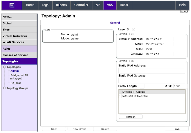
extremenetworks.com:topology:Admin:l3# ip 10.67.72.221/24
extremenetworks.com:topology:Admin:l3# mtu 1500
extremenetworks.com:topology:Admin:l3# gateway 10.67.72.1
extremenetworks.com:topology:Admin:l3# apply

extremenetworks.com:topology:Admin:l3# show
Interface IP 10.67.72.221 255.255.255.0
Factory default certificate/key
Factory default IPv6 certificate/key
Static IPv6 Address:
Static IPv6 Gateway: none
MTU: 1500
Gateway: 10.67.72.1
Dynamic IPv6 Address:
1: fe80::290:bff:fe40:d8ac 64

From GUI, you could [VNS] > [Topologies] > [Admin]


Oct 25, 2016

Wireless Radio and Battery Life

A wireless radio can perform one of four activities. It can be

  • Asleep
  • Idle and awake
  • Receiving 
  • Transmitting 
The goal of 802.11 power management, then, is to have wireless radios perform low-power activities, such as sleeping, as much as possible while performing high-power activities, such as transmitting, as little as possible. 

In 802.11, there are active mode and power save mode. 
Active mode : Stations and APs operate with the assumption that the station is always available to transmit and receive data

Power save mode: The AP is sleeping and unable to receive frame transmissions. 

When a station is in Power Save mode, it vacillates between one of two power stats, the doze state - saving the most battery life, and awake stat - either be idle, receiving, or transmitting. 

Every power management method is illustrated in the following steps and figures:

1. Before a station goes into the doze state, it sends a frame - null data frame, to indicate AP that power management is enabled. 


2. Once the station indicates that it is in Power Save mode, AP begins to buffer all frames destined to that station.


3. When the station goes into the awake state, it sends a frame to the AP in order to begin the data retrieval process.


4. When AP has finished sending all buffered data to the station, the station goes into the doze stat. 


802.11 power management 

802.11 power managment is the power management method from the original 80.11 standard. This affects the third and fourth steps of the basic power management.

Third Step. 

Fourth Step
Fifth Step


802.11e Unscheduled Automatic Power Save Delivery

U-APSD is the power management method from the 802.11e amendment.  It is part of the WMM-Power Save certification from Wi-Fi and is also required for 802.11n

above pictures from CWAP

Rate Selection

When 802.11 was introduced, multiple data rates have been supported. Every wireless adapter has defined minimum received signal and minimum SNR level. The following Table shows in vendor recommendations.

above the picture from CWAP

The Client station radios move away from an access point, they will shift down to lower bandwidth capabilities by using a process known as dynamic rate switching(DRS). The following picture shows the correlation between signal quality and distance from the AP. As a result, transmissions between tow 802.11b radio cards may be at 11 Mbps at 30 feet but at 2 Mbps at 150 feet.

above the picture from CWAP 


Fragmentation and Aggregation

802.11 standard allows for the fragmentation of unicast address frames. Fragmentation breaks an 802.11 frame into smaller pieces known as fragments.
The following picture shows an MSDU that has been fragmented into four fragments. Notice that the transmission of each fragment is followed by a SFIS and an ACK. 

 
above the picture from CWAP


On the other hand, if the network is experiencing a large amount of data corruption, lowering the 802.11 fragmentation setting may improve data throughput as you could image as the following situation. 

above the picture from cwap


In 802.11n, there are two types of frame aggregation were added, aggregate MAC service data unit and aggregate MAC protocol data. 

above pictures from CWAP

There are some restrictions for aggregating multiple MSDUs into a single MPDU. 
The MPDU can only contain MSDUs where the DA and SA values map to the same RA and TA value. All of the MSDUs must also have the same priority value. 
On the other hand, A-MPDU must all have the same receiver address. Also the individual MPDUs must all be of the same 802.11e QoS access category. 


Data Frame Address Fields

In 802.11 frame, you will see that the 802.11 data frame defines four address fields, named Address 1, Address 2, Address 3, Address 4.

The first step to understanding the addressing scheme of an 802.11 frame is to identify the logical addresses that used.

Source Address: This is the address where the frame is sent from.
Destination Address: This is the address where the frame is being sent to.
Transmitter Address: This is the address of the station that is transmitting the RF frame.
Receiver Address: This is the address of the station that is receiving the RF frame.
Basic Service Set Identifier: This is the basic server set ID of the AP.

As you could see the following picture,
  1. STA1 must send the frame to AP1.
  2. AP1 must forward that frame to AP2.
  3. AP2 must forward that frame to STA2 


QoS and Non-QoS Data Frames

The 802.11 standard defines 15 different data frames, as you could see from the following table.

above pictures from CWAP

As you could see above table, the most significant bit (MSB) of the subtype field (Bit b7) is defined as the quality of Service subfile, specify that the frame is a QoS data frame. 

QoS stations are capable of transmitting both QoS and Non-QoS data frames. It is  common to have a wireless network that consists of both QoS and non-QoS station. In this type of mixed environment, it is likely that QoS devices will transmit both QoS data frames and non-QoS frames depending upon the capabilities of the receiving station. 

The strange things for Data frames do not actually carry any data. In fact, almost half of the data frames defined do not carry any data. The frames that do carry data are as follows:

  • Data (simple data frame) Data + CF-Ack
  • Data + CF-Poll
  • Data + CF-Ack + CF-Poll QoS Data
  • QoS Data + CF-Ack
  • QoS Data + CF-Poll
  • QoS Data + CF-Ack + CF-Poll


 And the frames that do not carry any data re follows:


  • Null
  • CF-Ack
  • CF-Poll
  • CF-Ack + CF-Poll
  • Qos Null
  • QoS CF-Poll
  • QoS CF-Ack + CF-Poll 


 So, you may ask why have a data frame that does not carry data ? Sometimes a station needs to transmit special control information to an access point or another station, without actually transmitting any data. Client stations sometimes use Null data frames to enable or disable power save mode, which is indicated by a bit in the frame control field. Using the Null data frame allow a station to communicate with another device without requiring it to transmit data.


Oct 24, 2016

Block Acknowledgement

A Block ACK improves channel efficiency by aggregating several acknowledgements into one single acknowledgement frame. As shown in the following picture, the originator requests all the outstanding QoS data frames by sending a block acknowledgement request (BlockAckReq) frame.


Block ACK frame is shown by the following picture.


How to confirm ExtremeWireless Controller System Information

When you ordered ExtremeWireless contoller, you may first want to confirm the system information of wireless controller. Well, there are two ways to confirm it, from CLI and GUI.

From CLI
EWC-RDU-L17U32.extremenetworks.com# show system_state manufacturing
Manufacturing Information
    Manufacturing ID (Serial Number): 1542P-70030
    BIOS Version: 5.6.5
    Hardware Revision: 01
    Software Version: 10.11.02.0032
    Model: C35
    CPU Type: Intel(R) Atom(TM) CPU  C2718  @ 1.99GHz
    CPU Frequency (MHz): 2000.163
    Number of CPUs: 8
    Total Memory: 4045976 KB
    HW Encryption Support: Yes
    LAN 1  MAC address: 00:90:0B:xx:xx:xx
    LAN 2  MAC address: 00:90:0B:xx:xx:xx
    LAN 3  MAC address: 00:90:0B:xx:xx:xx
    LAN 4  MAC address: 00:90:0B:xx:xx:xx
    ADMIN  MAC address: 00:90:0B:xx:xx:xx

extremenetworks.com# show system_state info
System Information
System Up Time: 11 days,  1:17
- CPU Utilization: 8.13
- Memory Usage:
    Free: 87 %
- Disk Usage (1 Kbyte blocks)
    Partition    Total Space     Used     Available  Use %
         root       50477320   497240     48459716     1%
         home        2040016    32836      1986700     2%
          cdr        2032048    32812      1978756     2%
         logs        4080096    33020      4006112     1%
      reports        2032016    32812      1978724     2%
        trace        4088160    32812      4014384     1%
          tmp         131072      108       130964     0%
- System Temperature
    System Board Temperature: 26 C
    CPU Temperature: 50 C
- Fan Speed
    System Fan: 7584 RPM
- ESA0 Interface:
    Auto-negotiation: enabled
    Auto-negotiation capability includes:
      any speed and any duplex
    Interface State: down
- ESA1 Interface:
    Auto-negotiation: enabled
    Auto-negotiation capability includes:
      any speed and any duplex
    Interface State: up, 1000Mbps full duplex
- ESA2 Interface:
    Auto-negotiation: enabled
    Auto-negotiation capability includes:
      any speed and any duplex
    Interface State: down
- ESA3 Interface:
    Auto-negotiation: enabled
    Auto-negotiation capability includes:
      any speed and any duplex
    Interface State: down


If you want to confirm the information of AP, you could use show ap_inventory from wireless controller.

extremenetworks.com# show ap_inventory
Name:            15210586085A0000
Serial:          15210586085A0000
Desc:
Location:        -
Role:            Access Point
Software:        10.11.02.0032
Hardware:        Wireless AP3801i Internal
Port:            esa0
Wired MAC:       D8:84:66:xx:xx:xx
Poll Timeout:    15
Poll Interval:   3
Persistent:       off
LBS status:  enabled
Tunnel MTU: 1500
Broadcast Dissoc:  off
Assn:            DHCP
IP Address:      10.1.1.2
Netmask:         255.255.255.0
Gateway:         10.1.1.3
AC Search List:

adio Settings       Radio a     Radio b/g

802.11a              on          -
802.11b              _           off
802.11g              _           on
802.11n              on          on
DTIM Period          5           5
Beacon Period        100         100
RTS/CTS Threshold    2346        2346
Frag. Threshold      2346        2346
Channel              0           2462
Power Level          0           16
ATPC                 disabled    enabled
TX Power Adjust      0           0
TX Min Power         3           3
TX Max Power         14          16

BSS:MAC (radio a)
--
BSS:MAC (radio bg)
xx:xx:xx:xx:xx:xx

BSS:SSID (radio a)
--
BSS:SSID (radio bg)
SSID: MayniladWLAN

ExtremeWireless CLI Structure

Unlike Cisco wireless, ExtremeWireless C:I show the root context. Many of the commands move to a context. This kind of structure applies at every context level.


For example, if you want to see ap information from CLI. You need to go into ap root.